Problem: Your Drone Flies Into Things
You've got a drone that flies well in open space, but the moment it gets near a wall, a tree, or a person — it hits. GPS and barometers tell you where the drone is globally; they don't tell you what's 30cm in front of the nose.
Time-of-Flight (ToF) sensors solve this. They fire an infrared laser pulse, measure the round-trip time, and return a distance in millimeters — in under 20ms. No camera, no compute-heavy CV pipeline.
You'll learn:
- How ToF sensors work and why they beat ultrasonic for drones
- How to wire a VL53L1X to a flight controller over I2C
- How to write interrupt-driven firmware that triggers an emergency stop before a collision
Time: 45 min | Level: Advanced
Why This Happens
Stock drone firmware trusts the pilot (or the autopilot) to avoid obstacles. There's no sensor layer between "command received" and "motors spin." By the time a camera-based system processes a frame, a drone at 3 m/s is already 60ms closer — likely through whatever you were trying to avoid.
ToF sensors fix this at the hardware layer with minimal CPU overhead.
Common symptoms of no obstacle avoidance:
- Crashes during indoor flights or tight spaces
- Fly-aways when GPS position hold drifts toward a wall
- Damage on return-to-home if launch point has obstacles nearby
How Time-of-Flight Works
A ToF sensor emits a near-infrared (NIR) VCSEL laser pulse and starts an internal counter. When the reflected pulse returns to the SPAD (Single Photon Avalanche Diode) array, the counter stops. Distance is:
distance = (speed_of_light × time_of_flight) / 2
The VL53L1X (ST Microelectronics) does all of this on-chip and reports distance over I2C. Key specs for drone use:
| Spec | Value |
|---|---|
| Range | 4cm – 400cm |
| Accuracy | ±3% |
| Measurement time | 15–140ms (configurable) |
| Supply voltage | 2.6–3.5V |
| Interface | I2C (up to 400kHz) |
| Current draw | 19mA active |
For a drone with a 500mAh LiPo, 19mA is noise. That's the real win over LIDAR.
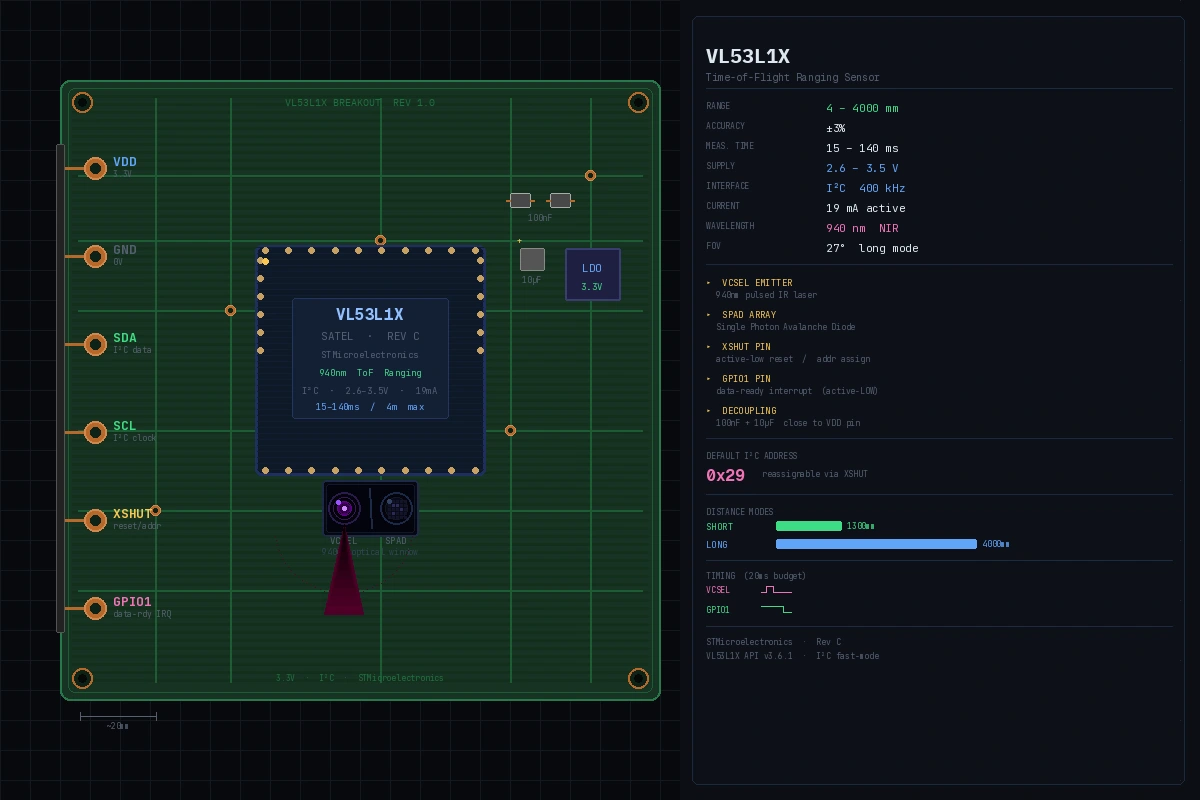 A breakout board with the VL53L1X. The dark window is the VCSEL emitter and SPAD array.
Hardware Setup
What You Need
- VL53L1X breakout board (SparkFun, Pololu, or Adafruit)
- Flight controller with I2C header (Pixhawk, Matek, or similar)
- 4 × 100Ω pull-up resistors (or use the breakout board's built-in ones)
- Short silicone wire (keep I2C runs under 30cm on a drone)
Step 1: Wire the Sensor
VL53L1X    →    Flight Controller
VDD        →    3.3V
GND        →    GND
SDA        →    I2C SDA
SCL        →    I2C SCL
XSHUT      →    GPIO pin (for multi-sensor setup)
GPIO1      →    GPIO pin (interrupt line)
Why XSHUT matters: Every VL53L1X powers up with the same default I2C address (0x29). If you're running multiple sensors (front, rear, left, right), hold all XSHUT pins LOW, then bring them HIGH one at a time and assign a unique address to each before releasing the next.
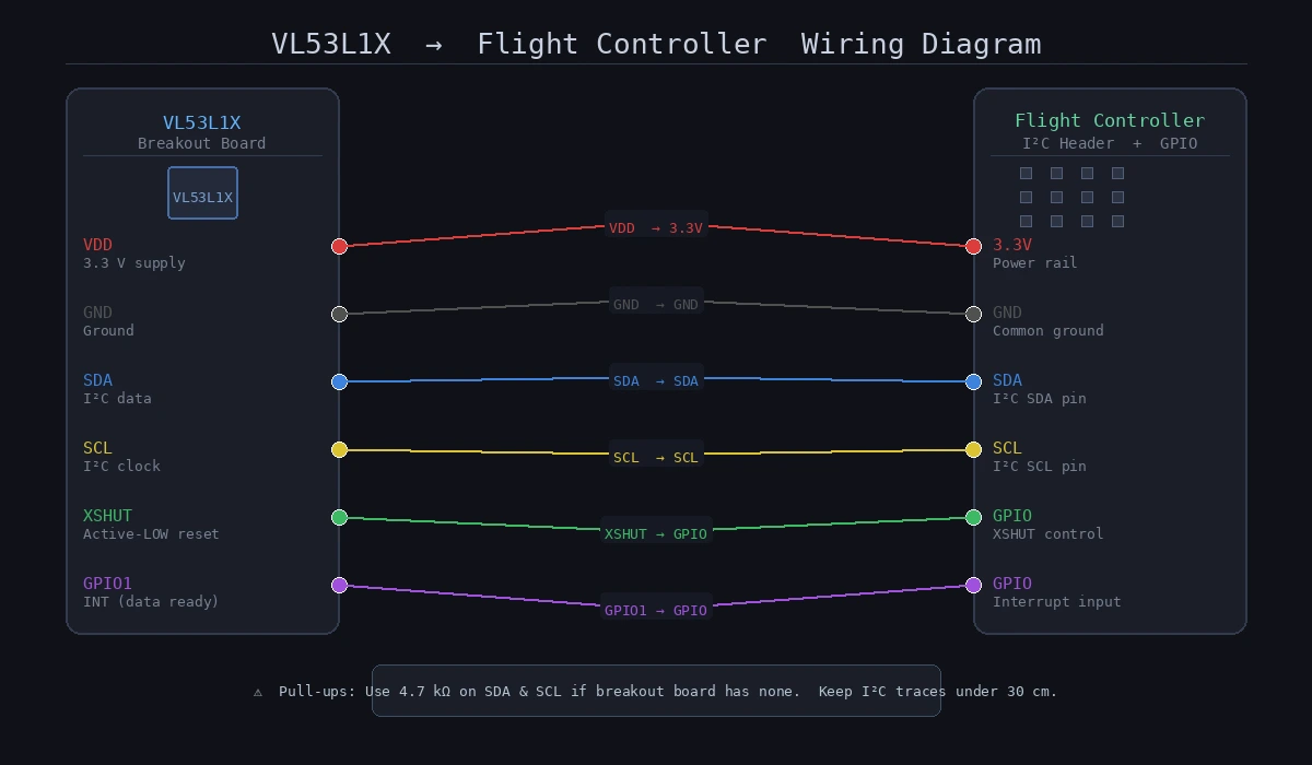 Keep SDA/SCL lines twisted together to reduce noise. Use 4.7kΩ pull-ups if the breakout board doesn't include them.
Firmware
This example targets an STM32-based flight controller running a bare-metal HAL or ChibiOS. Adapt the I2C calls to your platform.
Step 2: Initialize the Sensor
#include "VL53L1X_api.h"

#define TOF_I2C_ADDR  0x29  // Default address
#define TOF_XSHUT_PIN GPIO_PIN_5
#define TOF_INT_PIN   GPIO_PIN_6

static uint16_t tof_distance_mm = 0;
static volatile bool tof_data_ready = false;

void tof_init(void) {
    // Hold sensor in reset
    HAL_GPIO_WritePin(GPIOB, TOF_XSHUT_PIN, GPIO_PIN_RESET);
    HAL_Delay(10);

    // Release reset
    HAL_GPIO_WritePin(GPIOB, TOF_XSHUT_PIN, GPIO_PIN_SET);
    HAL_Delay(2); // Boot time: datasheet says 1.2ms min

    // Sensor boot check
    uint8_t state = 0;
    while (state == 0) {
        VL53L1X_BootState(TOF_I2C_ADDR, &state);
        HAL_Delay(2);
    }

    VL53L1X_SensorInit(TOF_I2C_ADDR);

    // Short mode = 1.3m max, better ambient light rejection
    // Long mode = 4m max, use outdoors with caution
    VL53L1X_SetDistanceMode(TOF_I2C_ADDR, 1); // 1 = Short

    // 20ms timing budget = fast, ~5% range accuracy loss vs 50ms
    // Use 50ms for precision hover, 20ms for obstacle avoidance
    VL53L1X_SetTimingBudgetInMs(TOF_I2C_ADDR, 20);
    VL53L1X_SetInterMeasurementInMs(TOF_I2C_ADDR, 25); // Must be >= timing budget

    // Interrupt fires when a new distance sample is ready
    VL53L1X_SetInterruptPolarity(TOF_I2C_ADDR, 0); // 0 = active LOW
    VL53L1X_StartRanging(TOF_I2C_ADDR);
}
Expected: Sensor initializes without hanging. If it loops forever on BootState, check your XSHUT wiring and 3.3V supply.
If it fails:
- HAL_I2C_ERROR_AF: Address mismatch. Confirm the I2C address with
i2c_scan(). - Sensor never boots: XSHUT must be pulled HIGH — check GPIO config.
Step 3: Read Distance via Interrupt
Polling burns CPU and adds latency. Use the GPIO1 interrupt line instead.
// Called by EXTI IRQ handler when GPIO1 fires
void HAL_GPIO_EXTI_Callback(uint16_t GPIO_Pin) {
    if (GPIO_Pin == TOF_INT_PIN) {
        uint8_t range_status;
        uint16_t raw_distance;

        VL53L1X_GetRangeStatus(TOF_I2C_ADDR, &range_status);
        VL53L1X_GetDistance(TOF_I2C_ADDR, &raw_distance);

        // Status 0 = valid range, 4 = wrap-around, 7 = rate fail
        // Only trust status 0 for obstacle logic
        if (range_status == 0) {
            tof_distance_mm = raw_distance;
            tof_data_ready = true;
        }

        // Clear interrupt or sensor will not fire again
        VL53L1X_ClearInterrupt(TOF_I2C_ADDR);
    }
}
Step 4: Implement the Obstacle Stop
#define OBSTACLE_WARN_MM   500   // 50cm: slow down
#define OBSTACLE_STOP_MM   200   // 20cm: emergency stop

typedef enum {
    FLIGHT_NORMAL,
    FLIGHT_SLOW,
    FLIGHT_ESTOP
} flight_state_t;

flight_state_t obstacle_check(void) {
    if (!tof_data_ready) return FLIGHT_NORMAL;

    tof_data_ready = false;
    uint16_t dist = tof_distance_mm;

    if (dist <= OBSTACLE_STOP_MM) {
        // Kill forward velocity immediately
        // In ArduPilot/PX4 MAVLink: set brake mode via RC override
        set_brake_mode();
        return FLIGHT_ESTOP;
    }

    if (dist <= OBSTACLE_WARN_MM) {
        // Scale max velocity inversely with proximity
        // At 50cm: 50% throttle cap. At 25cm: 10% throttle cap.
        float throttle_scale = (float)(dist - OBSTACLE_STOP_MM) /
                               (OBSTACLE_WARN_MM - OBSTACLE_STOP_MM);
        set_velocity_limit(throttle_scale);
        return FLIGHT_SLOW;
    }

    clear_velocity_limit();
    return FLIGHT_NORMAL;
}

// Call this from your main flight loop (typically 400Hz)
void flight_loop(void) {
    flight_state_t state = obstacle_check();

    if (state == FLIGHT_ESTOP) {
        log_event("OBSTACLE_STOP dist=%dmm", tof_distance_mm);
        // Notify GCS if connected
        mavlink_send_statustext(MAV_SEVERITY_WARNING,
                                "Obstacle detected, braking");
    }
}
Why the scale instead of a hard cutoff at 50cm: A sudden velocity clamp at 50cm creates a jerky, unpredictable flight experience. Linear scaling gives the pilot feedback through gradually reduced responsiveness before the hard stop at 20cm.
Step 5: Multi-Sensor Setup (Optional)
For full 360° avoidance, add sensors in each cardinal direction. All start at address 0x29 — reassign them at boot:
#define TOF_FRONT_ADDR  0x30
#define TOF_REAR_ADDR   0x31
#define TOF_LEFT_ADDR   0x32
#define TOF_RIGHT_ADDR  0x33

// GPIO pins for each sensor's XSHUT
const uint16_t xshut_pins[] = {
    GPIO_PIN_5,  // Front
    GPIO_PIN_6,  // Rear
    GPIO_PIN_7,  // Left
    GPIO_PIN_8   // Right
};

const uint8_t tof_addresses[] = {
    TOF_FRONT_ADDR, TOF_REAR_ADDR,
    TOF_LEFT_ADDR,  TOF_RIGHT_ADDR
};

void tof_init_all(void) {
    // 1. Pull all XSHUT LOW (all sensors off, all silent)
    for (int i = 0; i < 4; i++) {
        HAL_GPIO_WritePin(GPIOB, xshut_pins[i], GPIO_PIN_RESET);
    }
    HAL_Delay(10);

    // 2. Wake each sensor, assign address, move to next
    for (int i = 0; i < 4; i++) {
        HAL_GPIO_WritePin(GPIOB, xshut_pins[i], GPIO_PIN_SET);
        HAL_Delay(5);

        // Sensor is at default 0x29 — reassign before waking next
        VL53L1X_SetI2CAddress(TOF_I2C_ADDR, tof_addresses[i]);
        HAL_Delay(2);
    }

    // 3. Initialize all sensors at their new addresses
    for (int i = 0; i < 4; i++) {
        // Re-run init sequence at new address
        VL53L1X_SensorInit(tof_addresses[i]);
        VL53L1X_SetDistanceMode(tof_addresses[i], 1);
        VL53L1X_SetTimingBudgetInMs(tof_addresses[i], 20);
        VL53L1X_SetInterMeasurementInMs(tof_addresses[i], 25);
        VL53L1X_StartRanging(tof_addresses[i]);
    }
}
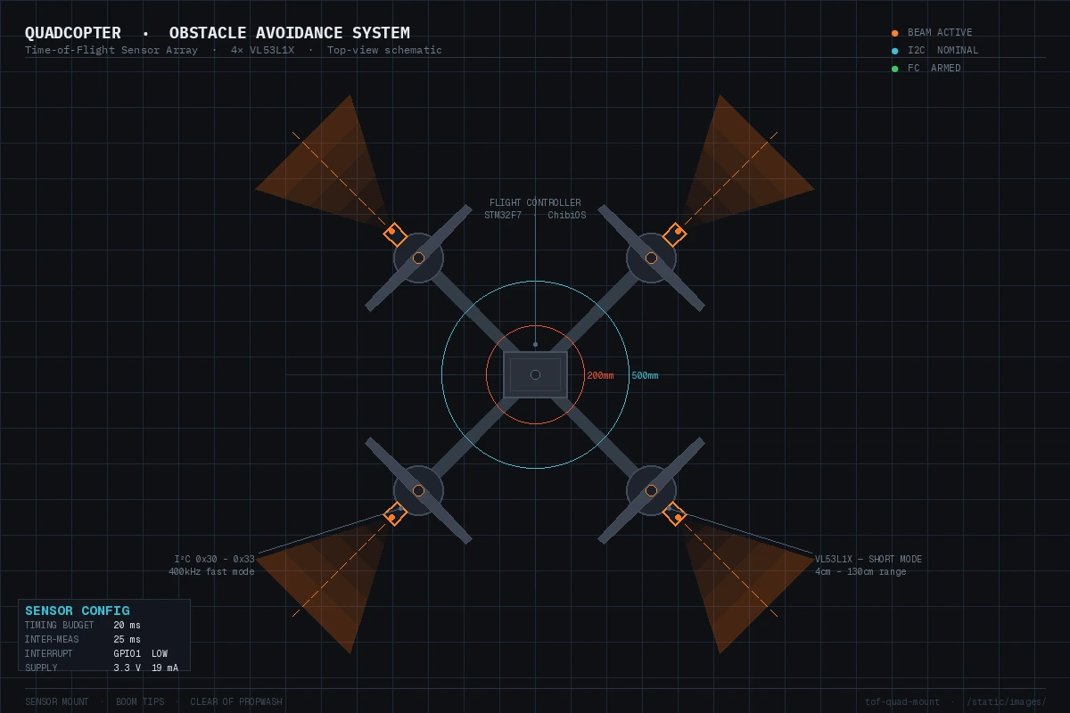 Mount sensors at the boom tips facing outward for maximum coverage. Keep them clear of propwash.
Verification
Power up the drone (props OFF) and run this test harness:
// Debug output over UART/USB
void tof_debug_loop(void) {
    while (1) {
        if (tof_data_ready) {
            printf("Distance: %d mm | State: %s\n",
                tof_distance_mm,
                tof_distance_mm <= OBSTACLE_STOP_MM ? "ESTOP" :
                tof_distance_mm <= OBSTACLE_WARN_MM ? "SLOW"  : "OK");
            tof_data_ready = false;
        }
        HAL_Delay(10);
    }
}
# Monitor serial output (115200 baud)
screen /dev/ttyUSB0 115200
You should see readings updating at ~40Hz (25ms inter-measurement period), with distance values that match a ruler held in front of the sensor within ±1cm.
Then test the logic: slowly move your hand toward the sensor and confirm:
- "SLOW" appears at ~50cm
- "ESTOP" appears at ~20cm
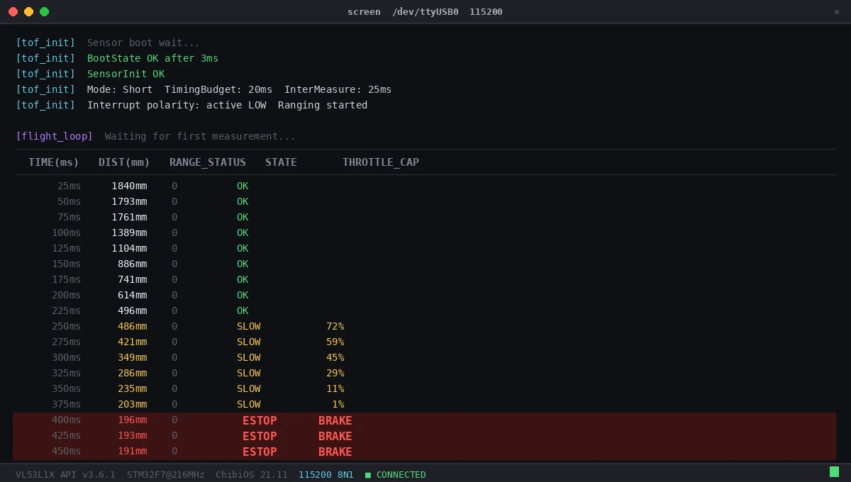 Readings at 40Hz with status transitions visible as hand approaches
What You Learned
- ToF sensors give you sub-20ms obstacle detection with 19mA current draw — practical on any drone
- Interrupt-driven reads (GPIO1 line) are essential; polling at 400Hz will starve your flight loop
- Gradual velocity scaling beats a hard cutoff for pilot UX and stability
- The XSHUT address-reassignment trick is the only sane way to run multiple VL53L1X sensors on one I2C bus
Limitations:
- VL53L1X struggles with black, absorptive surfaces (matte black foam, dark carpet) — distance can read short or fail entirely
- Specular reflections (glass, mirrors) can return false short readings
- Outdoor performance degrades in direct sunlight above ~50klux — use short mode and tune accordingly
- This pattern blocks the flight loop if I2C hangs; add a watchdog or DMA-based I2C for production code
When NOT to use this: If your use case involves detecting thin obstacles like wire fences or monofilament, ToF's beam divergence (~27° in long mode) will miss them. Use a camera-based approach for those scenarios.
Tested on: VL53L1X rev C silicon, STM32F7 @ 216MHz, ChibiOS 21.11, ST's VL53L1X API v3.6.1