Problem: Your Pneumatic Gripper Has No Precision Control
You built a soft pneumatic gripper but it only goes fully open or fully closed. Controlling grip force — the whole point of soft robotics — requires PWM-driven solenoid valves and a feedback loop your microcontroller can actually run.
You'll learn:
- How to wire a solenoid valve safely to a 3.3V/5V microcontroller
- How to modulate pressure with PWM instead of on/off switching
- How to add a pressure sensor for closed-loop grip force control
Time: 20 min | Level: Intermediate
Why This Happens
Most pneumatic gripper tutorials wire the solenoid valve directly to a relay — which is just a digital on/off switch. That gives you two states: inflated or deflated. It works for pick-and-place with rigid objects, but soft grippers are designed to conform and hold fragile objects with variable force. Without PWM control and pressure feedback, you're wasting the core advantage of soft robotics.
Common symptoms:
- Gripper crushes soft objects or fails to grip firm ones
- No way to hold position at partial inflation
- Pressure spikes causing actuator delamination or seal failure
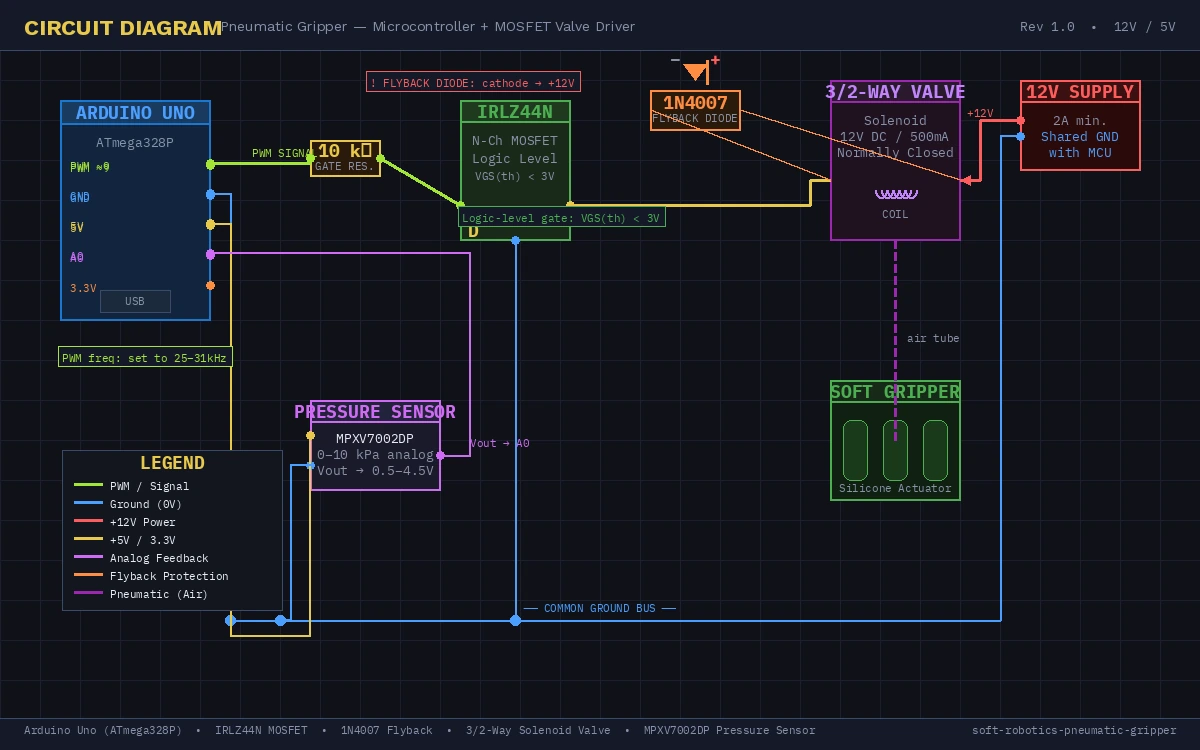 Full circuit: Arduino Uno, IRLZ44N MOSFET, flyback diode, and 12V solenoid valve
Solution
Step 1: Wire the Solenoid Valve Correctly
Solenoid valves run on 12V and draw 500mA–2A — far beyond what a microcontroller pin can source. You need a logic-level MOSFET between the MCU and the valve.
Parts needed:
- IRLZ44N or similar logic-level N-channel MOSFET (gate threshold <3.3V)
- 1N4007 flyback diode (valve coil is inductive — it will spike and destroy your MCU without this)
- 10kΩ gate resistor
- 12V solenoid valve (3/2-way, normally-closed recommended)
- External 12V supply
MCU PWM Pin → 10kΩ resistor → MOSFET Gate
MOSFET Drain → Solenoid Valve (−)
MOSFET Source → GND (shared with MCU GND)
Solenoid Valve (+) → 12V supply
1N4007 diode across valve terminals (cathode to +12V)
Why the flyback diode matters: When you cut PWM low, the solenoid coil collapses its magnetic field and generates a reverse voltage spike of 50–100V. Without the diode, this goes straight into your MOSFET drain and kills it in milliseconds.
 Diode orientation is critical — stripe (cathode) faces the +12V rail
If it fails:
- MOSFET gets hot immediately: Gate threshold too high for your MCU voltage — use a dedicated gate driver like TC4427
- Valve clicks but doesn't open: Insufficient gate drive voltage — measure gate-source voltage with a multimeter, should be >4V
Step 2: Set Up PWM on Your Microcontroller
For an Arduino Uno, pins 3, 5, 6, 9, 10, and 11 support PWM. For Raspberry Pi Pico, use any GP pin with hardware PWM (GP0–GP15, even-numbered).
Arduino Uno (AVR):
const int VALVE_PIN = 9;  // Timer1 on Uno — 490Hz default

void setup() {
  pinMode(VALVE_PIN, OUTPUT);

  // Increase PWM frequency to reduce solenoid audible whine
  // Timer1 prescaler = 1 → ~31kHz, above human hearing
  TCCR1B = (TCCR1B & 0b11111000) | 0x01;
}

void setGripForce(float pressure_pct) {
  // pressure_pct: 0.0 (fully deflated) to 1.0 (fully inflated)
  // Clamp to safe operating range — most soft actuators fail above 80% duty
  pressure_pct = constrain(pressure_pct, 0.0, 0.8);
  int duty = (int)(pressure_pct * 255);
  analogWrite(VALVE_PIN, duty);
}

void loop() {
  setGripForce(0.4);  // 40% — gentle grip for fragile objects
  delay(2000);
  setGripForce(0.0);  // release
  delay(1000);
}
Why 31kHz matters: The default 490Hz PWM causes the solenoid to physically click 490 times per second — audible and mechanically stressful. At 31kHz the valve's armature can't mechanically follow the switching, so it settles at an average position proportional to duty cycle.
Raspberry Pi Pico (MicroPython):
from machine import Pin, PWM
import time

VALVE_PIN = 0  # GP0
PWM_FREQ = 25_000  # 25kHz — above audible range

valve = PWM(Pin(VALVE_PIN))
valve.freq(PWM_FREQ)

def set_grip_force(pressure_pct: float) -> None:
    # u16 range: 0–65535
    # Cap at 80% to protect actuator from over-pressure
    pressure_pct = max(0.0, min(pressure_pct, 0.8))
    duty = int(pressure_pct * 65535)
    valve.duty_u16(duty)

# Gentle grip cycle
set_grip_force(0.4)
time.sleep(2)
set_grip_force(0.0)
time.sleep(1)
Expected: Valve hums quietly (not clicking) and the gripper inflates to a partial, stable position.
If it fails:
- Gripper fully inflates at any duty cycle >0: Valve response threshold is higher than PWM average — try increasing minimum duty to 30%
- Pico resets under load: Add a 100µF electrolytic cap across the 12V supply rails to absorb current spikes
Step 3: Add Closed-Loop Pressure Feedback
Open-loop PWM works, but pressure in a soft actuator depends on ambient temperature, actuator fatigue, and load. A cheap MPXV7002DP or BMP388 sensor closes the loop.
Hardware: Connect a 0–10kPa analog pressure sensor to an ADC pin. Most MCU ADC inputs are 0–3.3V or 0–5V.
// Arduino — closed-loop pressure control
const int VALVE_PIN = 9;
const int PRESSURE_PIN = A0;
const float TARGET_KPA = 5.0;    // Target grip pressure
const float KP = 0.05;           // Proportional gain — tune this first
const float KI = 0.001;          // Integral gain — eliminates steady-state error

float integral = 0.0;
float current_duty = 0.0;

float readPressureKPa() {
  int raw = analogRead(PRESSURE_PIN);
  // MPXV7002DP: Vout = 0.5V at 0kPa, 4.5V at 10kPa
  // At 5V ADC reference: raw 0-1023 maps to 0-5V
  float voltage = (raw / 1023.0) * 5.0;
  return (voltage - 0.5) * (10.0 / 4.0);  // kPa
}

void loop() {
  float actual_kpa = readPressureKPa();
  float error = TARGET_KPA - actual_kpa;

  integral += error;
  integral = constrain(integral, -100, 100);  // Prevent windup

  float output = (KP * error) + (KI * integral);
  current_duty = constrain(current_duty + output, 0.0, 0.8);

  analogWrite(VALVE_PIN, (int)(current_duty * 255));
  delay(50);  // 20Hz control loop — fast enough for pneumatics
}
Why PI and not PID: Derivative control amplifies sensor noise. Pneumatic systems are slow enough (time constants of 100–500ms) that a PI controller converges cleanly.
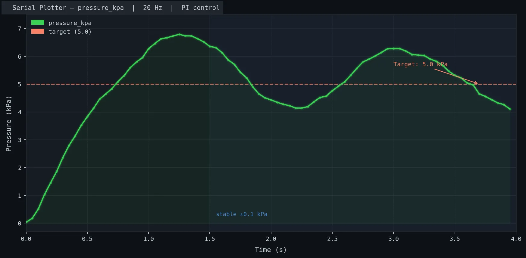 Pressure overshoots once then settles at 5kPa within ~1 second
If it fails:
- Pressure oscillates wildly: KP is too high — halve it and retry
- Pressure never reaches target: KI is too low or there's a physical leak — check actuator seams with soapy water
Verification
Upload the closed-loop sketch, open Serial Monitor at 115200 baud, and add a print statement to watch pressure:
Serial.print("kPa: ");
Serial.println(actual_kpa);
You should see: Pressure ramp up to target, overshoot by <20%, and stabilize within 2–3 seconds. If it takes longer, reduce KP by 50%.
kPa: 0.12
kPa: 1.87
kPa: 4.43
kPa: 5.31
kPa: 5.08
kPa: 4.97
kPa: 5.01
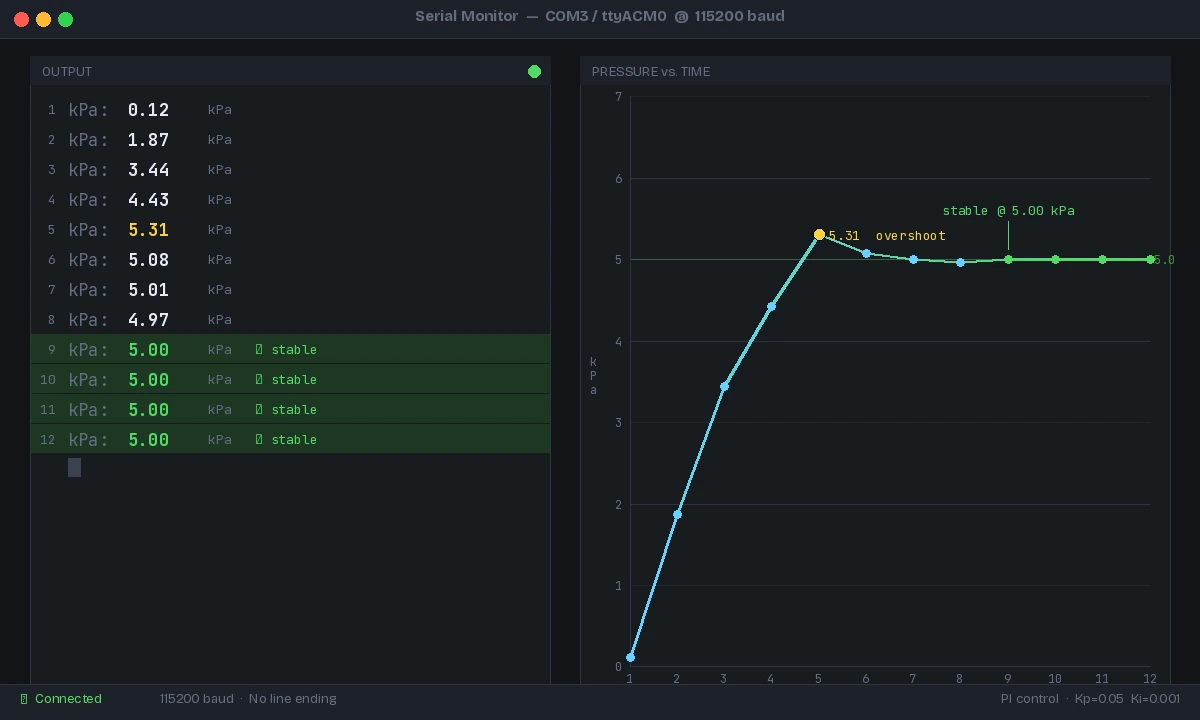 Stable output within 10 readings — PI gains are well-tuned
What You Learned
- A logic-level MOSFET + flyback diode is the correct interface between an MCU and an inductive solenoid load — a relay works but gives you no modulation
- PWM frequency must exceed the solenoid's mechanical bandwidth (~1kHz) to get analog-like pressure control
- PI control is sufficient for pneumatics — skip the D term to avoid noise amplification
- Cap duty cycle at 80% to stay within safe actuator pressure limits
Limitation: This approach controls one valve and one gripper chamber. Multi-chamber grippers (for finger-independent control) require one MOSFET + valve per channel, but the same firmware pattern scales directly.
Tested on Arduino Uno R3 (ATmega328P), Raspberry Pi Pico (RP2040 MicroPython 1.23), MPXV7002DP sensor, Festo MEBH-5/2 solenoid valve